
According to Bernoulli's theorem, ideal fluids can be conserved in streamlined or steady flow. Fluids such as liquids and gases move under pressure, velocity, and elevation in response to this theorem. As a result of this theorem, the flow is stable, or laminar, with minimal compressibility or viscosity (internal friction). As per Bernoulli's theorem, fluids flowing horizontally will have lower pressure at sites with greater fluid velocity than those with a lower velocity. Mathematician Daniel Bernoulli first derived Bernoulli's theorem (1738) in Switzerland. According to its definition, "the flow of a fluid has a constant mechanical energy."
In order to maintain a constant volume flow rate, incompressible fluids must accelerate when they approach a tight restricted segment. This is why a small nozzle on a hose enables water to flow more quickly. If the water accelerates at a constriction, it is accumulating kinetic energy. Giving kinetic energy is the same as doing labour. The fluid must be being worked on from outside if a section of it is speeding up. On the figure, streamlines can be seen flowing from left to right. The highlighted volume of water accelerates as it enters the confined zone. P1 exerts force on water which causes it to push to the right and produce positive work. In the fluid, because the fluid's pressure P2 pushes in the opposite direction of its motion, negative work is produced.

If P1 is wider/slower than P2, then P1 must exert greater pressure than P2. Bernoulli's principle refers to the inverse connection between pressure and speed at a location in a fluid.

Bernoulli's theorem for pressure distribution is applied to a moving incompressible fluid. It is important to take into account that the pipe diameter and the temperature remain constant throughout the system. A conduit carries fluid from point 1 to point 2 as shown in the figure above. The pump produces energy to force the flow to go upward. Consider a channel filled with one pound of fluid at point 1.
P1 lb/ft2 is the pressure at this point. If the fluid's average velocity is V1 lb/sec and its specific volume is V1 ft3 /lb. Point 1 is located at h1 height above the horizontal bottom plane. A pound of fluid has potential energy equal to h1 ft. lb. at point 1. The fluid moves at V1, so a pound of fluid has a kinetic energy of V12 /2gc ft.Lb. This equation is based on the fluid's average velocity (V) in the system. In fact, the average velocity is not the same as the mean velocity. Fluid passing through a channel will produce the following kinetic energy per pound

A fluid's weight is determined by its mass, the radius of its channel is determined by its radius, and a local velocity is determined by its distance from its axis. Due to the different velocity distributions inside the channel at different locations, only the actual velocity distribution, and not the integral, can be calculated. A separate velocity distribution curve is generated for each scenario. Thus, in the actual sense, kinetic energy is expressed as V2/gc, where is a correction factor for differences in velocity at different sites in the channel. In the case where turbulent flow = 2, viscous flow = 1

The velocity V2 is equal to the pressure P2 at point 2, and the volume of fluid is V2* at point 2.
The principle of conservation of energy holds true for the system between points 1 and 2. A pump is believed to add energy to the system. Fluid weight equals ‘W’ lbs/lb of energy. Friction converts some of the energy into heat which, when exposed to constant temperature, dissipates into the environment through radiation.
Friction results in a loss of energy of 'F' pounds per lb of fluid. Balance between points 1 and 2 results in the system's total energy

If lb/ft3 is the density of fluid ' ρ', then

In that case, the equation becomes:

Throughout the above equation, energy is expressed in terms of one pound of fluid entering the system, with mass being expressed as kilograms.
The resulting turbulent eddies allow the flow to separate from the boundary, resulting in heat loss as a result of heat dissipation by radiation. The pressures (P1, V1), and velocity (P2, V2) of the liquid flowing through the narrower and wider pipes, respectively, are the pressures (P1), the velocity (V1), and the discharge (Q), respectively.
Q = A1V1 + A2V2
Fluid force acting in the direction of flow on a controlled volume is described as
P1A1 + P1 (A2 – A1) – P2A2 = (P1 – P2) A2
When Newton's second law is used for the rate of change of momentum as well as the head loss due to sudden enlargement of two sections '1' and '2', when Bernoulli's equation is applied, we get

In order to express equation (3), use the continuity equation,

A sudden enlargement of the head is expressed by equations (3) and (4).

A vena-contract is formed between the wider and narrower pipes as liquid flows from one to the other, followed by further widening to completely fill the narrower pipe. Many eddies have formed between the vena contracta and the wall of the pipe, resulting in considerable energy loss. An almost similar flow pattern occurs in this region as a result of sudden expansion.
A sudden contraction of the head results in the following loss of head:


A liquid flow in a pipe at a mean velocity V.
Energy loss by obstruction in flow passage
Figure illustrates how a flow obstruction results in a sudden reduction of the pipe's cross-sectional area followed by an abrupt expansion of the stream beyond the obstruction, which results in energy loss.

As an example, imagine a pipe flow in which an obstruction with maximum cross-sectional area 'a' is placed in the pipe. The flow passage is reduced to (A - a), and a vena-contracta is formed a certain distance from the vena-contracta, beyond which the flow is uniform. Vc and V are the respective velocities of the section where the flow is uniform, so that loss of head is determined from the velocities at the vena-contracta and at the section where the flow is uniform.

In order to maintain a constant volume flow rate, incompressible fluids must accelerate when they approach a tight restricted segment. This is why a small nozzle on a hose enables water to flow more quickly. If the water accelerates at a constriction, it is accumulating kinetic energy. Giving kinetic energy is the same as doing labour. The fluid must be being worked on from outside if a section of it is speeding up. On the figure, streamlines can be seen flowing from left to right. The highlighted volume of water accelerates as it enters the confined zone. P1 exerts force on water which causes it to push to the right and produce positive work. In the fluid, because the fluid's pressure P2 pushes in the opposite direction of its motion, negative work is produced.
If P1 is wider/slower than P2, then P1 must exert greater pressure than P2. Bernoulli's principle refers to the inverse connection between pressure and speed at a location in a fluid.
Bernoulli's equation
In Bernoulli's equation, gravitational potential energy is taken into account as a general and mathematical variant of the Bernoulli's principle. In Bernoulli's equation, the pressure, speed, and height at two points (1 and 2) are described by a fluid whose density is ' ρ '.Bernoulli's theorem for pressure distribution is applied to a moving incompressible fluid. It is important to take into account that the pipe diameter and the temperature remain constant throughout the system. A conduit carries fluid from point 1 to point 2 as shown in the figure above. The pump produces energy to force the flow to go upward. Consider a channel filled with one pound of fluid at point 1.
P1 lb/ft2 is the pressure at this point. If the fluid's average velocity is V1 lb/sec and its specific volume is V1 ft3 /lb. Point 1 is located at h1 height above the horizontal bottom plane. A pound of fluid has potential energy equal to h1 ft. lb. at point 1. The fluid moves at V1, so a pound of fluid has a kinetic energy of V12 /2gc ft.Lb. This equation is based on the fluid's average velocity (V) in the system. In fact, the average velocity is not the same as the mean velocity. Fluid passing through a channel will produce the following kinetic energy per pound
A fluid's weight is determined by its mass, the radius of its channel is determined by its radius, and a local velocity is determined by its distance from its axis. Due to the different velocity distributions inside the channel at different locations, only the actual velocity distribution, and not the integral, can be calculated. A separate velocity distribution curve is generated for each scenario. Thus, in the actual sense, kinetic energy is expressed as V2/gc, where is a correction factor for differences in velocity at different sites in the channel. In the case where turbulent flow = 2, viscous flow = 1
The velocity V2 is equal to the pressure P2 at point 2, and the volume of fluid is V2* at point 2.
The principle of conservation of energy holds true for the system between points 1 and 2. A pump is believed to add energy to the system. Fluid weight equals ‘W’ lbs/lb of energy. Friction converts some of the energy into heat which, when exposed to constant temperature, dissipates into the environment through radiation.
Friction results in a loss of energy of 'F' pounds per lb of fluid. Balance between points 1 and 2 results in the system's total energy
If lb/ft3 is the density of fluid ' ρ', then
In that case, the equation becomes:
Throughout the above equation, energy is expressed in terms of one pound of fluid entering the system, with mass being expressed as kilograms.
Applications of Bernoulli theorem
- With Bernoulli's equation, one can determine how much fluid flows through a pipe.
- It enables us to quantify the change in velocity and pressure experienced by a fluid flowing from one pipe with one cross-sectional area to another with another cross-sectional area. As a fluid moves from a larger conduit to a smaller pipe, its velocity and pressure rise. This connection is especially significant in preventing water pipe malfunctions by maintaining constant fluid pressure. An overburden of pressure can cause the pipe to explode, causing serious damage.
- It may be used to compute the lift force on an airfoil if the fluid flow behaviour near the foil is known.
- In order to calculate an aircraft's airspeed, Pitot tubes and static ports are used. The airspeed indicator is calibrated using Bernoulli's principle such that it shows the indicated airspeed suitable to the dynamic pressure.
- A De Laval nozzle employs Bernoulli's principle to generate force by converting pressure energy generated by fuel combustion into velocity.
- In addition to a Venturi meter, an orifice plate that is inserted into the pipeline reduces its inside diameter can be used to measure flow speed. In the case of an incompressible fluid, a decrease in diameter may result in an increase in fluid flow speed. In order to achieve Bernoulli's principle, the lower diameter zone must fall under pressure.
- If a tank has an opening at the bottom, then the top drain rate can directly be determined using Bernoulli's equation and can be found to be proportional to the depth of the fluid in the tank. The viscosity slows down the drain rate. A discharge coefficient represents this, and is determined by the Reynolds number and orifice geometry.
- When the gripper and surface are in contact, the Bernoulli grip establishes a non-contact adhesive force.
Energy Loss
Large-scale turbulence is caused by changes in fluid velocity (either in magnitude or direction) in a flow. Radiation ultimately dissipates a portion of the energy that the flowing fluid possesses, which is referred to as a loss of energy. Change in velocity can result in a loss of energy when sudden pipe enlargement or contraction occurs, when a pipe enters from a large vessel, when a pipe exits, when there is an obstruction in the flow passage, when there are gradual contractions or enlargements, when there are bends, and various pipe fittings, etc. Because of their small magnitudes, frictional losses in long pipes are classified as 'minor' losses. There are only a couple of small losses along the flow path. For each of the aforementioned cases, we discuss analytical expressions for the loss of energy.Energy loss by sudden enlargement
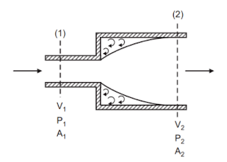
The pipe has a cross-sectional area A1, and it carries a liquid with a specific weight w. The pipe is connected to another pipe of greater cross-sectional area A2. As the flow passage of a smaller pipe narrows abruptly, the liquid released cannot follow the abrupt change in flow boundary.The resulting turbulent eddies allow the flow to separate from the boundary, resulting in heat loss as a result of heat dissipation by radiation. The pressures (P1, V1), and velocity (P2, V2) of the liquid flowing through the narrower and wider pipes, respectively, are the pressures (P1), the velocity (V1), and the discharge (Q), respectively.
Q = A1V1 + A2V2
Fluid force acting in the direction of flow on a controlled volume is described as
P1A1 + P1 (A2 – A1) – P2A2 = (P1 – P2) A2
When Newton's second law is used for the rate of change of momentum as well as the head loss due to sudden enlargement of two sections '1' and '2', when Bernoulli's equation is applied, we get
In order to express equation (3), use the continuity equation,
A sudden enlargement of the head is expressed by equations (3) and (4).
Energy loss by sudden contraction
The area of a pipe carrying a particular liquid containing specific weight w at one point abruptly reduces from A1 to A2, as seen in Figure. The sudden contraction in the pipe geometry leads to curved streamlines where sections ‘1′ and ‘2′ meet, causing the liquid to be accelerated. This results in an unknown variation of pressure at the annular face, which cannot be measured. Between section 1 and the converging part, there is no significant energy loss.A vena-contract is formed between the wider and narrower pipes as liquid flows from one to the other, followed by further widening to completely fill the narrower pipe. Many eddies have formed between the vena contracta and the wall of the pipe, resulting in considerable energy loss. An almost similar flow pattern occurs in this region as a result of sudden expansion.
A sudden contraction of the head results in the following loss of head:
Energy loss at pipe entrance
Losses at the entrance to a pipe are also known as 'inlet losses'. If a large vessel (or tank) is used to enter the pipe, this can occur. There is a sudden contraction of the flow pattern. Loss of head at an entrance with a sharp corner can be expressed as follows:Energy loss at pipe exit
Depending on the end of the pipeline that carries liquid, the outlet may be unconnected or connected to a reservoir. As the liquid exits the pipe, it has a certain amount of kinetic energy based on the velocity of the liquid flowing in the pipe that is dissipated in the reservoir either in the form of free jets or turbulence based on the condition at the outlet. By using Equation above and conditions for which A2 ---> ∞, the loss can be determined. Thus, the loss at the pipe exit would be expressed as the following:A liquid flow in a pipe at a mean velocity V.
Energy loss by obstruction in flow passage
Figure illustrates how a flow obstruction results in a sudden reduction of the pipe's cross-sectional area followed by an abrupt expansion of the stream beyond the obstruction, which results in energy loss.
As an example, imagine a pipe flow in which an obstruction with maximum cross-sectional area 'a' is placed in the pipe. The flow passage is reduced to (A - a), and a vena-contracta is formed a certain distance from the vena-contracta, beyond which the flow is uniform. Vc and V are the respective velocities of the section where the flow is uniform, so that loss of head is determined from the velocities at the vena-contracta and at the section where the flow is uniform.
Get subject wise printable pdf notesView Here

No comments:
Post a Comment
Please don't spam. Comments having links would not be published.